

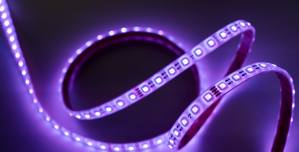

Using a UL-listed Class 2 LED power supply, it is possible to power an RGB LED strip light as a fixed red, green, blue, or mixed color (such as yellow or purple) by selecting the appropriate conductors while maintaining conductor sizing and load calculations based on the full rated output of the RGB strip.
This guide is intended for lighting professionals, contractors, architects, and designers seeking a clean, reliable method to specify and install a fixed-color RGB strip light without a controller, while remaining aligned with NEC intent and manufacturer requirements.
Understanding RGB Strip Light Wiring Basics
A single-color LED strip light typically uses two conductors:
- Positive (+)
- Negative (-)
An RGB LED strip light, by contrast, uses four conductors:
- Black: Common positive (+)
- Red: Red channel negative (-)
- Green: Green channel negative (-)
- Blue: Blue channel negative (-)
In a typical RGB system, a color changing controller selectively switches the negative channels to mix colors. When a controller is not used, a fixed color can be achieved by directly connecting one or more of these negative conductors to the power supply.
This method relies solely on field wiring at accessible connection points and does not alter the internal circuitry of the RGB strip light.
The Key Concept: Treating an RGB Strip Light Like a Single-Color Strip Light
To achieve a fixed color output:
- Connect the black (positive) conductor from the RGB strip light to the positive (+) output of a UL-listed Class 2 LED power supply.
- Connect one or more color conductors (red, green, blue) to the negative (–) output, depending on the desired color.
- Individually cap and secure all unused conductors using listed connectors or insulation methods.
By doing this, only the selected LED channels are energized, producing a permanent, static color without the use of a controller.
RGB Color Selection & Wire Hookup Table
The table below shows which conductor(s) are connected to the negative (–) terminal to achieve each fixed color:
| Desired Color | Wires Connected to Negative (–) | Resulting Output |
|---|---|---|
| Red | Red | Red |
| Green | Green | Green |
| Blue | Blue | Blue |
| Yellow | Red + Green | Yellow |
| Purple (Magenta) | Red + Blue | Purple |
| Cyan | Green + Blue | Cyan |
| White | Red + Green + Blue | White |
Example: Wiring an RGB Strip Light for Fixed Red or Yellow Output
For Red Only
- Ensure the power supply is disconnected from power.
- Connect the black wire from the RGB strip light to the positive (+) output of the Class 2 power supply.
- Connect the red wire to the negative (–) output.
- Individually cap and secure the green and blue wires using listed connectors or heat shrink.
- Restore power – only the red LEDs will illuminate.

For Yellow (Red + Green)
- Disconnect the power supply from power.
- Keep the black wire connected to the positive (+) output.
- Using a listed connector (such as a WAGO connector or appropriately sized wire nut), connect the red and green wires together and terminate them to the negative (–) output.
- Cap and secure the blue wire so it cannot make contact.
- Restore power – the strip light will illuminate yellow.

To change to another fixed color, simply move which color conductor(s) are connected to the negative terminal, following the same process.
Best Practices for Professional Installations
- Always use a UL-listed Class 2 LED power supply rated for the voltage of the RGB strip light (commonly 12V or 24V DC).
- Load calculations must be based on the full rated wattage of the RGB strip as listed by the manufacturer, regardless of how many color channels are energized. Conductor sizing, power supply capacity, and run lengths must follow the strip’s full-load specifications.
- All splices and terminations must be made using listed connectors and installed in accordance with NEC 110.14 and manufacturer instructions.
- Unused conductors must be individually capped or insulated and secured so they cannot contact other conductors or grounded surfaces.
- This method is best suited for static architectural applications such as coves, niches, signage, and accent details where color will not change.
- If future color control or dimming across channels is required, an color changing controller should be specified instead.
Code Compliance Note
This wiring method is acceptable for Class 2 low-voltage LED systems when installed in accordance with the manufacturer’s instructions, NEC Article 411, and NEC 110.3(B). All components, including LED strips, power supplies, conductors, and connectors, must be UL-listed and rated for the intended application and environment.
Final Thoughts
By directly wiring an RGB LED strip to a Class 2 power supply, you can achieve up to seven fixed colors using a simplified wiring approach, eliminating the need for a controller while maintaining compliance with NEC intent and manufacturer requirements. For permanent, single-color installations, this method offers a streamlined, reliable solution with fewer components and reduced points of failure.
For additional guidance on RGB strip light selection, power supply sizing, or code-compliant installation details, our support team is always available to help.
Industry professionals can take it a step further by joining our Pro Program, which provides access to expert lighting support, project-ready resources, and exclusive benefits designed to make specifying and installing LED lighting easier and more efficient.


